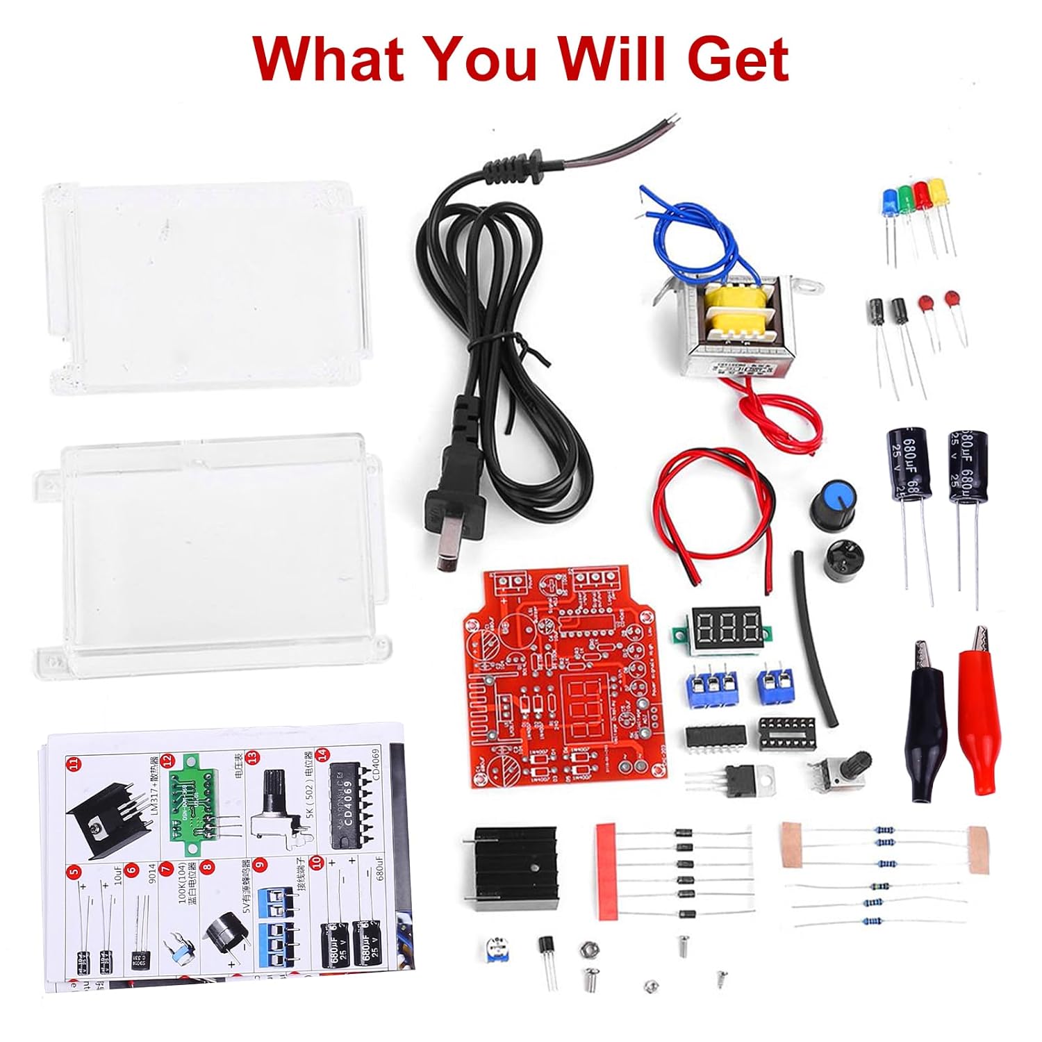
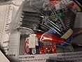
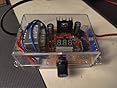
This is a nice kit. The enclosure is a nice addition, and it being clear means you can look at the circuit while you blow it up during learning. =) And, BONUS: when you release the magic smoke, it will still be kept inside the container and can be re-harvested!! 🙂
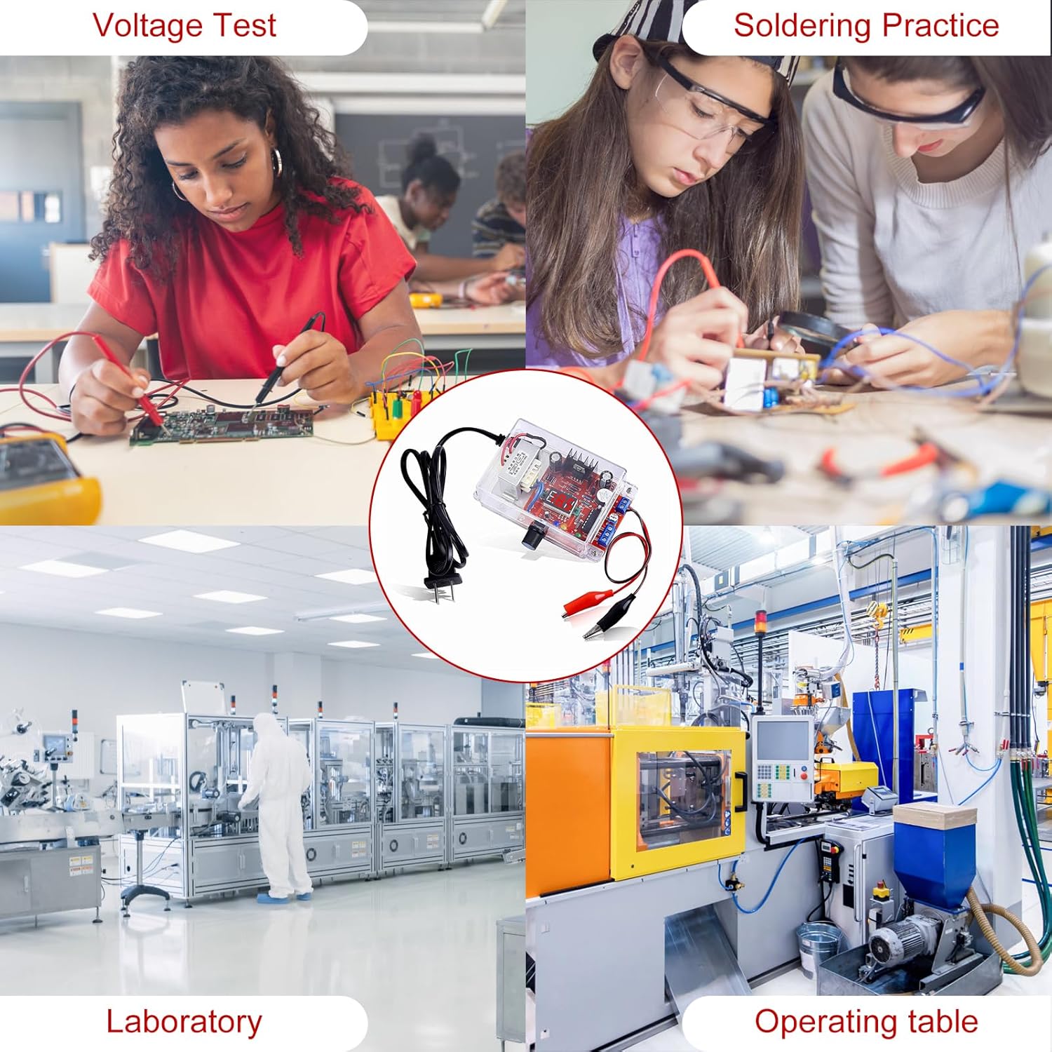
In general, this kit is for experimenting with power supplies. It is relatively safe, and will be easy to hack if desired. It is not intended to provide a lot of power, which means you can easily see how power supplies behave when they deal with circumstances outside of their capabilities.
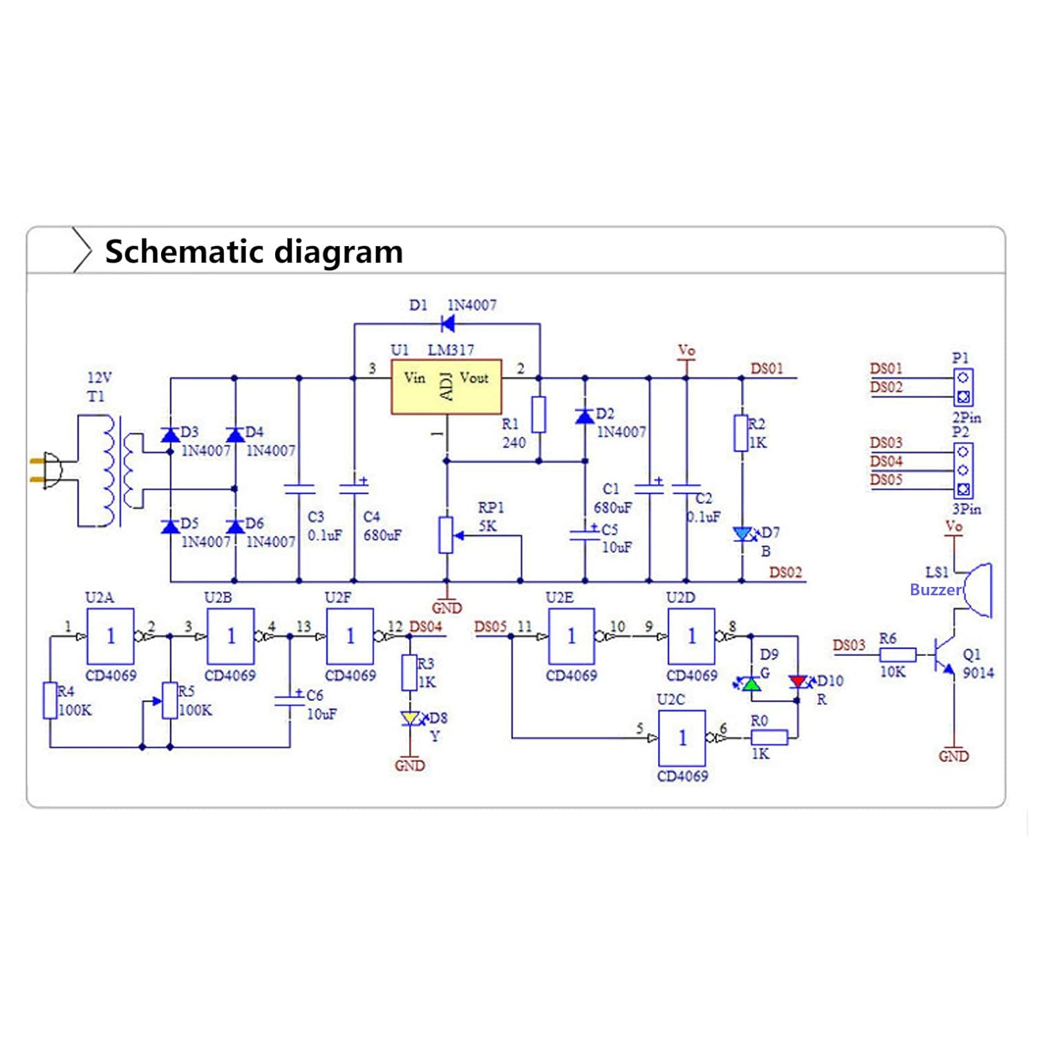
The manual is pretty good. There are some spelling and grammar errors, but it is understandable. It has a good explanation of how the circuit works. I will add my own comments on that below, but it is well written for the price, and for the target user. Note that there is a minor error in the parts list pictogram. It says there are 4x 1N4007 diodes. However, the Part List is correct (there are actually 6, and 6 are included in the kit). It's just a mistake in box 1 of the part photos.
The kit came with several extra screws in case you lose any, which is good.
In my opinion, this kit is a great way to learn about:
– Line noise
– Input ripple
– Output ripple
– Dropout voltage
– Load regulation
– How to read a datasheet (LM317)
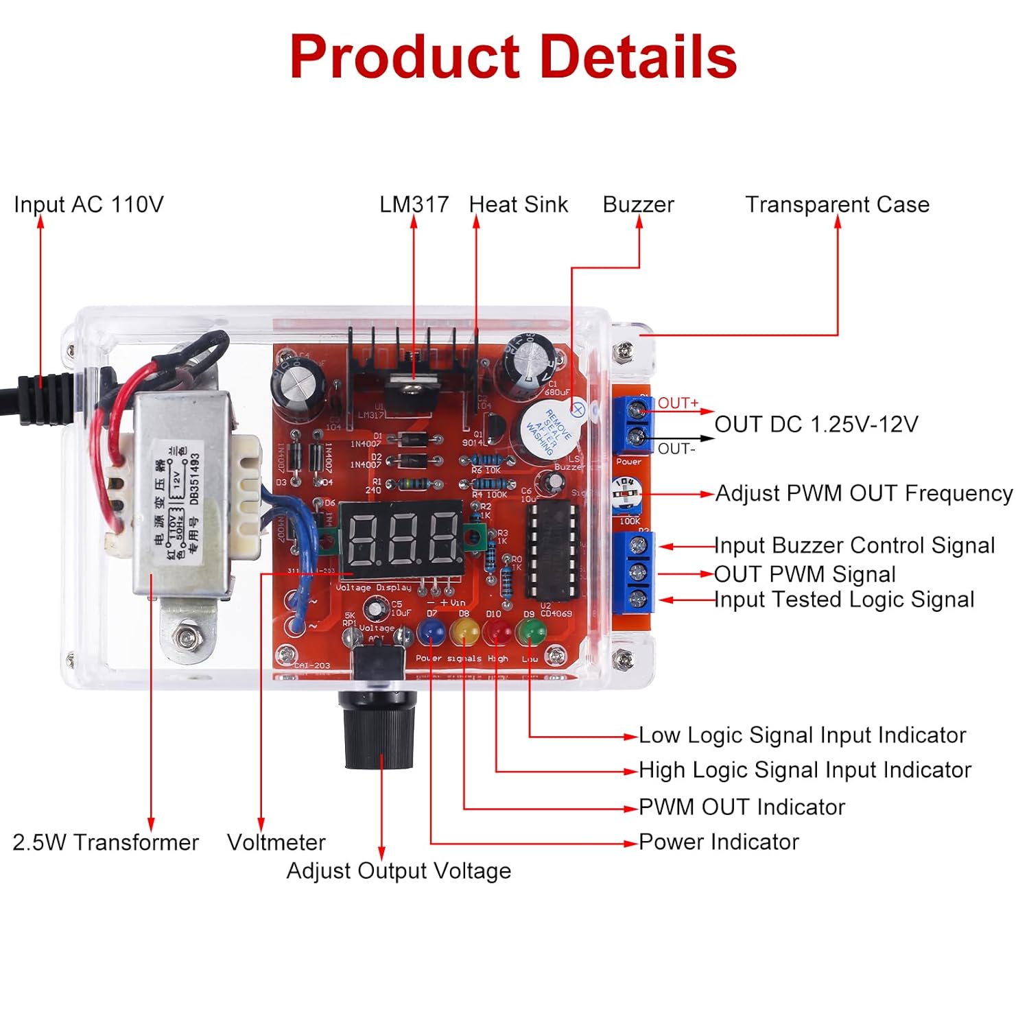
There is a logic input circuit, but for me it only detected LOW, not HIGH. I checked the polarity of the LED and it is correct. Not sure what I did wrong there. It's probably just a mistake I made in assembling it.
There is an adjustable interval timer with an output pin that can be used for something. I don't really have a use for it, but it's an interesting feature. The frequency of the "Signal output" terminal can be set using the "signal adjust" potentiometer next to the terminals. The frequency is adjustable between ~320mHz and ~10Hz.
SAFETY WARNING: When you build this, DO NOT IGNORE the heat shrink tubing of the mains wires. Be very careful with these since shorting them will pop your circuit breaker and make a beautiful, terrifying spark. 🙂 You can shrink the tubing with a soldering iron by holding the iron very close right underneath the tubing after sliding it over the exposed wire. It will take a minute, but it works just fine. You do not need a heat gun to do it! A hair dryer might even work, but I usually just use the tip of my iron. Don't touch the iron to the tubing, though. It smells really nasty and will mess up your tip. You just want the heat to float off the tip and bake it a little.
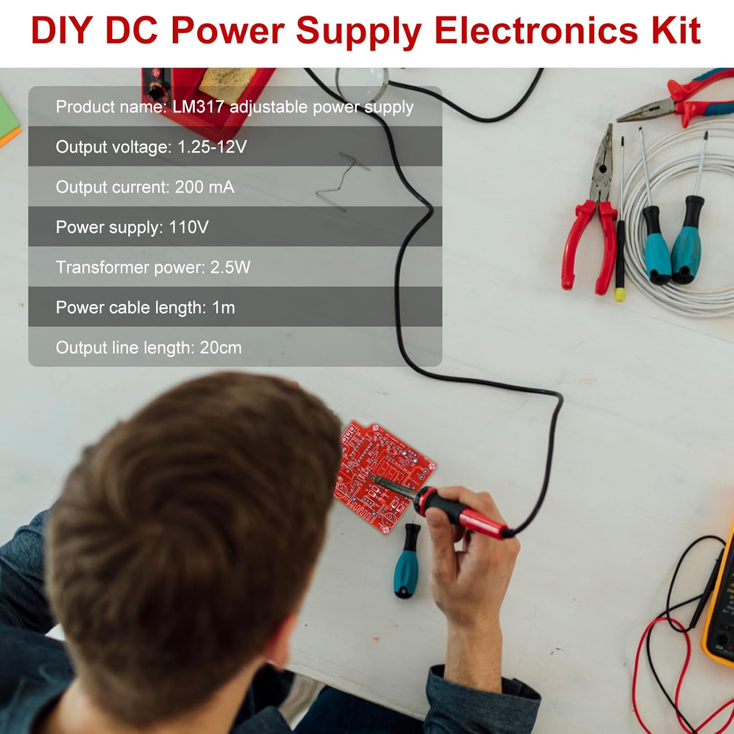
As stated in the manual, the output power of this circuit is very low. This is intentional. Higher output power could be hazardous to people who are learning.
It is important to understand that even though the voltage can be set to 13.6V (the output voltage of the transformer minus the drop of the two diodes for each half of the bridge rectifier), the circuit will not provide power at that level. This is because the regulator has a drop voltage. In order to regulate the output voltage, the input voltage must be 1.2V greater than the desired output voltage. Therefore, the true usable voltage range is equivalent to what is given in the manual pamphlet: 1.25-12V. 1.25V is the minimum voltage the LM317 can provide because that is what it uses as an internal voltage reference.
If you attempt to set the voltage above 13.1V or so, you will see significant voltage noise (100mV or above). This is because the regulator is no longer fully regulating its input voltage. Since the input voltage is coming from a mains transformer, the frequency will be 2 times that of the input voltage of that transformer. In the US, that is 60Hz. The bridge rectifier flips the negative half of that voltage positive, resulting in a 120Hz "bunny hop" waveform. If you were to measure the voltage at C4, you would see this waveform. If you set the voltage of the output greater than 13 or so volts, you will see the same shape waveform on the output from the regulator, due to the reasons stated above.
It is also important to note that exceeding the output power rating (2.5W is what the manual states) will result in poor regulation as well (ripple and voltage drop). This is declared in the manual.
After building the circuit, I measured the voltage ripple under various load conditions:
With no load:
– @12.2V: less than 5mV ripple
– @1.2V: less than 5mV ripple
With a load of 100mA, the ripple was:
– @12.2V: Voltage reduced to 8.4V, 400mV ripple
– @1.2V: less than 6mV ripple
With a constant current load of 25mA:
– @11.8V: ~100mV ripple
– @1.20V: ~5mV ripple
The manual says that 200mA of current can be supplied, so I determined the maximum voltage at which 200mA could be supplied with satisfactory ripple (let's say 100mVpp). This turned out to be about 3.75V. This might be improved by experimenting with the circuit and increasing the capacitance of C1 (you can add more in parallel). The power supply output voltage will change more slowly, since there is a lot of stored energy at the previous voltage when it is being lowered. It will also take a while to raise the voltage with more capacitance on the output. There is a tradeoff between smooth voltage level and rapid output regulation. I would start with at least 2500uF of capacitance if you want to try this out. (It comes with 680, so just boost it from there).
I noticed that, at 200mA output current at 3.75V, the case got a little bit warm after about 15 minutes. The regulator will release the most heat at LOWER voltages. This is because it has to dissipate power in order to reduce the voltage on the input to the voltage on the output. At higher output voltages, you will be limited by how much power can be delivered. At lower voltages, that same limit exists, but the majority of the power is not delivered to the load, but rather dissipated as heat.
Again, the kit is good for experimenting and learning how regulator circuits work. This power supply design has a lot of similarities with power supplies that I have designed in the real world. Usually, I would use better regulator chips (LM317 is not a precision or low dropout regulator).
Some fun modifications that could be done to this kit to make it cooler:
1. Cut a hole in the case and install a switch for the mains HOT wire. This would allow the kit to remain plugged in and remove mains current from the input of the transformer.
2. Cut a square hole in the top and move the LED display to the top and add a fogged window. The LED display is very bright (maybe a bit too bright).
3. Replace RP1 with a 10-turn potentiometer. This will give much more precise voltage adjustment.
4. Add a current meter to the output of the regulator.
5. Add a ripple limit detector to the output of the regulator (series capacitor, rectifier, low pass filter, and comparator).
6. Add a thermometer to the transformer and/or regulator heat sink.


Report